
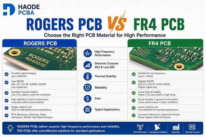

Most laminate selection arguments end the same way: someone quotes a dielectric constant, someone else quotes a price, and the board gets built on whatever the fabricator had in stock. That works until the design misses its loss budget, fails a flammability requirement, or costs four times what it needed to. The three materials in this comparison cover the large majority of RF and high-speed designs below 30 GHz, and choosing between them is more structured than it first appears.
The specification that catches almost everyone
Rogers publishes two different dielectric constants for its RO4000 series, and confusing them is the single most common cause of impedance being wrong on the first build.
The process specification value is the one quoted in most datasheets and marketing material: 3.48 ± 0.05 for RO4350B and 3.38 ± 0.05 for RO4003C, measured by a clamped stripline method at 10 GHz. The design value, which is what you should actually feed into your field solver, is higher: approximately 3.66 for RO4350B and 3.55 for RO4003C. The difference comes from the measurement method, not from any variation in the material itself.
Use the process value in a 50-ohm microstrip calculation and your trace will come out too wide, landing your impedance low by roughly five to eight percent depending on geometry. This is not a fabrication error, and no amount of arguing with your supplier will fix it after the fact. Confirm which value your stackup was calculated against before releasing the design, and state it explicitly in the fabrication notes so the question cannot be answered differently by two people.
RO4003C and RO4350B: nearly identical, one critical difference
Both are thermoset hydrocarbon-ceramic laminates with woven glass reinforcement. Both have a glass transition temperature above 280°C, absorb very little moisture, and — crucially for cost — process using standard FR-4 equipment and chemistry. No sodium etch, no specialised plasma cycle, no exotic lamination profile. This is why they dominate commercial RF work rather than the lower-loss PTFE grades sitting above them in the catalogue.
The loss difference between the two is real but modest: a dissipation factor of 0.0027 for RO4003C against 0.0037 for RO4350B at 10 GHz. On a short trace this is negligible. Across a long feed network at 20 GHz it becomes worth measuring, and on a large antenna array where the same loss is repeated across dozens of branches it can be the difference between meeting and missing a link budget.
The difference that actually drives selection, though, is flammability. RO4350B carries a UL 94V-0 rating. RO4003C does not. If your product must meet a flammability requirement — which covers most telecommunications infrastructure, most medical equipment and a great deal of industrial hardware — the decision is made for you regardless of the loss numbers. Designers who pick RO4003C for its lower Df and then discover the certification requirement late lose weeks re-qualifying a board that was electrically fine.
Thermal and mechanical properties that matter in the field
Loss and dielectric constant dominate the conversation, but the properties that determine whether a board survives are thermal and mechanical.
Glass transition temperature above 280°C for both RO4000 grades means the laminate is not softening during lead-free reflow, which matters if your assembly involves multiple thermal cycles or rework. FR-4 grades commonly sit between 135 and 180°C, and while that is sufficient for most assembly profiles, the margin is far smaller.
Thermal conductivity is the property most often overlooked. RO4350B conducts heat at roughly 0.69 W/m/K against approximately 0.3 for typical FR-4 — better than twice as effective at moving heat out of a power amplifier footprint. Where a design places an active device directly on the RF laminate, this changes junction temperature meaningfully and can remove the need for a separate thermal solution.
Moisture absorption follows the same pattern. The RO4000 grades take up a small fraction of what FR-4 does, which matters because absorbed moisture raises both dielectric constant and loss. A narrowband design that drifts between a dry winter bench and a humid summer enclosure is often exhibiting moisture behaviour rather than a design flaw.
When FR-4 is genuinely the right answer
FR-4 is not a compromise material at low frequency; it is the correct one. Below roughly 1 to 2 GHz with short trace runs, its higher loss simply does not consume enough of your budget to matter, and it costs a fraction of any high-frequency laminate.
The problem with FR-4 is not average loss but consistency. Its dielectric constant is not tightly controlled, varies with the resin-to-glass ratio across the panel, and drifts with temperature and moisture. On a 2.4 GHz antenna feed this produces tuning that shifts between builds and sometimes across a single panel. If your design is narrowband, or if impedance repeatability matters more than absolute performance, that variability is the reason to move up — not the loss figure everyone quotes.
There is also a middle path worth knowing about. Many designs do not need high-frequency material on every layer. A hybrid construction places RO4350B only on the layers carrying RF, with FR-4 cores handling the digital and power sections beneath. This captures most of the electrical benefit at a fraction of the material cost, and the RO4450F bonding prepreg exists specifically to make that construction practical.
Side-by-side
| Property | FR-4 (typical) | RO4003C | RO4350B | Selection impact |
| Dk @10 GHz (process) | ~4.2–4.6 | 3.38 ± 0.05 | 3.48 ± 0.05 | FR-4 value is uncontrolled |
| Design Dk | not specified | ~3.55 | ~3.66 | Use this in the field solver |
| Df @10 GHz | ~0.02 | 0.0027 | 0.0037 | Loss budget on long traces |
| UL 94V-0 | Yes | No | Yes | Often decides the choice |
| Tg | ~135–180°C | >280°C | >280°C | Assembly and field thermal |
| Thermal conductivity | ~0.3 W/m/K | ~0.6 W/m/K | ~0.69 W/m/K | Heat out of active devices |
| Processing | Standard | Standard | Standard | No PTFE cost penalty |
Cost, and where it actually comes from
Engineers tend to assume the laminate price difference drives the board price difference. It contributes, but panel utilisation usually matters more. High-frequency laminates come in a narrower set of panel sizes than FR-4, and a design that nests poorly into those sizes can add more to the unit cost than the material premium itself. Ask your fabricator how many of your boards fit per panel before finalising the outline. Trimming four millimetres off a board edge occasionally increases yield per panel by an entire row, and that single change can outweigh weeks of negotiating on price.
The second cost factor is stocking. A fabricator holding standard RO4000 thicknesses in inventory quotes shorter lead times and avoids minimum-purchase surcharges on odd thicknesses. When comparing quotes, ask what is actually on the shelf. A Rogers PCB supplier that keeps the common thicknesses in stock will usually beat a cheaper quote carrying a three-week material wait, once you price in the schedule risk and the cost of holding an assembly line idle.
A practical selection sequence
1. Establish your loss budget at the highest operating frequency, not the centre frequency.
2. Check whether a flammability rating is required. If yes, RO4003C is eliminated.
3. Check whether impedance repeatability across builds is critical. If yes, FR-4 is eliminated.
4. Assess whether an active device dissipates enough heat into the laminate to make thermal conductivity a factor.
5. Calculate trace geometry using the design Dk, not the process specification.
6. Ask your fabricator which thicknesses are in stock, then adjust the stackup to match if the electrical design permits.
7. Verify panel utilisation before locking the board outline.
When to move beyond the RO4000 series
The RO4000 family stops being the right answer in three situations. Above roughly 30 GHz, dissipation factor starts to dominate and PTFE-based materials such as RT/duroid 5880 or RO3003 become necessary despite their processing difficulty. Where dielectric constant must remain stable across a wide temperature range — automotive radar being the obvious case — RO3003 has a markedly lower thermal coefficient of Dk. And where a design needs miniaturisation through a high dielectric constant, RO3010 at Dk 10.2 shrinks resonant structures considerably.
Each of those steps raises fabrication difficulty sharply, because all three are PTFE-based and none can be plated without surface activation. Discuss the move with a Rogers PCB manufacturer before committing to it in the design, since PTFE handling is a genuine capability question rather than a purchasing one, and not every shop that quotes the material runs it as routine production.
Closing
The selection logic is simpler than the datasheets suggest. Flammability requirements and impedance repeatability eliminate options faster than loss figures do, and the design-versus-process Dk distinction causes more first-build failures than any material property. Settle those three points before comparing prices, and the remaining decision is usually obvious enough to make in an afternoon.